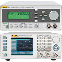
• 회사소개
    • CEO인사말
    • 연혁
    • CI소개
    • 회사위치
  • 제품소개
    • PROBE STATION
    • KEISOKU-GIKEN
    • FLUKE
    • ROHDE & SCHWARZ
    • MEGGER
    • GE DRUCK
    • ISOTECH
    • IMC , GRAPHTEC
    • 제작품
  • 뉴스
    • NOTICE
    • NEWS
  • 상담메일

FLUKE-280 Series
RCL Meter – PM6303
Date:2014-04-11

FLUKE-396/397


73


Waveforms

Waveforms

Standard waveforms: sine, square, triangle, ramp, sinc, pulse, noise, Gaussian as well as dc

Sine

Range

0.1 mHz to 50 MHz

Resolution

7 digits or 0.1 mHz

Accuracy

< 1 ppm for 1 year

Temp. coefficient

< 1 ppm/°C

Harmonic distortion and non related spurious below 10 MHz

< 0.1 % THD to 100 kHz (2000 waveform points)

< –55 dBc to 1 MHz

< –40 dBc to 5 MHz

< –35 dBc to 10 MHz

< –22 dBc to 50 MHz

Square

Range

0.1 mHz to 50 MHz

Resolution

0.1 mHz or 7 digits

Rise and fall times

< 10 ns

Triangle

Range

0.1 mHz to 12.5 MHz

Resolution

0.1 mHz or 7 digits

Accuracy

1 ppm for 1 year

Linearity error

< 0.1 % to 100 kHz

Pulse

Range

0.1 mHz to 12.5 MHz

Delay

0 % to 99.9 % of period

Rise and fall times

0 % to 99.9 % of period

High time

0 % to 99.9 % of period

Resolution

0.1 %

Arbitrary Waveforms

Stored waveforms

396: Up to 4096

397: Up to 4096 each channel

Waveform length

16 to 4 M points

Vertical resolution

14 bits

Sample clock range

100 mHz to 125 MHz

Waveform sequencing

Up to 4096 segments may be linked. Minimum segment duration 1 µs. Segments can be looped up to 1,000,000 times

Amplitude

Output impedance

50 Ω

Amplitude Range

10 mVpp to 10 Vpp (20 mVpp to 20 Vpp into open circuit)

Accuracy

< 1 % ± 25 mV between 1 V to 10 Vpp into 50 Ω

Flatness

± 5 % to 10 MHz; ± 20 % to 50 MHz

DC offset

± 4.5 V into 50 Ω. DC offset plus signal peak limited to ± 10 V. DC offset attenuated with amplitude range

Output Filters

50 MHz Elliptic and 2 MHz Elliptical

Modulation Modes

Triggered burst

Each active edge of the trigger signal will produce one burst of the carrier waveform, waveforms starts from point n and completes at point n-1

Gated

The selected waveform is output continuously at the programmed frequency while the selected gate signal is true

Waveforms

All standard and arbitrary

Carrier frequency

125 Msample/s for ARB and Sequence. 2.5 MHz or the maximum of selected waveform

No. of cycles

1 to 1,000,000

Trigger source

Manual trigger key, adjacent channel or internal trigger generator or external trigger input or remote trigger command

Trigger rate

Internal trigger generator: 0.1 Hz to 2 MHz; External signal: dc to 2 MHz

Start/stop phase

± 360 ° , settable to 0.1 ° subject to waveform frequency and type

Frequency sweep

Manual, continuous, triggered; linear or logarithmic sweep; up or down. Variable sweep marker.

Sweep range

1 mHz to 125 MHz

Sweep time

1 ms to 999 s

Sweep trigger source

External trigger input or remote trigger command

Tone switching

FSK tone switching for all waveforms

External AM

Via rear panel BNC input, dc-500 kHz for all standard and arbitrary waveforms

Outputs and Inputs

Main outputs

396

Single channel

397

Two channel

Sync outputs

Front panel BNC connector generates sync pulse synchronous with output waveform. In FM and sweep modes this output is synchronous with sample clock frequencies

Ext. trigger

DC to 2 MHz. Threshold nominally TTL level; maximum input 5 V. Selectable as positive rising edge or negative falling edge. Minimum pulse width 20 ns for trigger and gated modes

AM input

0 V to +5 V (5 Vpp) produce 100 % modulation

Ref clock in

Input for an external 10 MHz reference clock. Threshold nominally TTL level.

SCLK output, SCLK input and DSUB connector

Connect instruments to achieve synchronization. DSUB 9- pin connector and cable supplied.

Inter-Channel Operation

Inter-channel modulation

The waveform from any channel may be used to amplitude modulate (AM) the adjacent instrument/channel. Alternatively, any number of channels may be modulated (AM) with the signal at the modulation input socket.

Carrier frequency

Entire range for selected waveform

Carrier waveforms

All standard and arbitrary waveforms

Modulation freq.

DC to 500 kHz

Modulation depth

0 % to 100 %

Inter-channel synchronization

397

Both channels are tightly synchronized in phase and waveform start. Channel 2 has sample clock divider for arbitrary and sequenced waveforms.

Phase resolution

397

1 sample clock period of channel 2

Skew error

397

± 2 ns

Inter-instrument synchronization

Two or more instrument may be slaved to one master instrument. Each Slave can have a unique phase resolution relative to the Master.

Phase error

4 points

Skew error

+/-20ns Typically with 20c”m coax cable


General Specifications

Waveform Software

ArbExplorer Software for Windows is supplied with each instrument. This provides full waveform creation, editing and management including an equation editor, clipboard import/export and freehand drawing.

Interface types

396

GPIB and RS-232

397

GPIB, USB and Ethernet

Remote control

Full remote control facilities are available through the interfaces

RS-232

Variable Baud rate, 115 k Baud. 9-pin D-connector

GPIB

Conforms with IEEE-488.1 and IEEE-488.2

Ethernet

397

Twisted pair 10/100Base-T, auto negotiation

USB

397

Type A receptacle, version 2.0

Display

396

20 character x 4 row alphanumeric LCD

397

3.5 in color LCD reflective, 320 x 240 pixels, back-lit

Size

88 x 415 x 212 mm (H x D x W)

Weight

6 kg (13 lb)

Power

85 V to 265 V, 48 – 63 Hz, 60W

Operating temperature range

0 °C to 50 °C

Operating humidity (non condensing)

11 °C to 30 °C 85 % RH;

31 °C to 40 °C 75 % RH;

41 °C to 50 °C 45 % RH

Storage range

–20 °C to + 60 °C

Environmental

Operating altitude: 10,000 feet

Storage: 15,000 feet

Pollution degree 2

Safety

Complies with EN61010-1

EMC

Complies with EN61326, CE marked

  • KEISOKU-GIKEN
    • 양방향전원
  • ROHDE & SCHWARZ
    • 오실로스코프
    • 스팩트럼 분석기
    • 네트워크 분석기
    • 신호발생 분석기
    • EMC 시스템
    • 방송신호 측정
    • RF 파워미터,파워센서
  • MEGGER
    • 절연저항측정
      • 저저항측정기
      • 1KV 절연저항계
      • 5KV/10KV 절연저항계
    • 내전압시험기
    • 계전기 시험기
    • 변압기 시험기
    • 차단기 시험기
    • 배터리 테스트기
    • 절연진단 장비
    • 멀티미터 및 검전기
    • 다기능 계측기
  • GE DRUCK
    • 압력측정장비
      • 압력교정기준기
      • 휴대용 압력교정기
    • 온도측정장비
      • 온도교정 표준기
      • 온도교정 기준기
      • 산업용 온도교정기
    • 항공계측교정기
    • 습도측정장비
    • 항온항습챔버
    • 온도센서
    • 초음파측정기
  • ISOTECH
    • 산업용온도교정기
    • 다기능온도교정기
    • 고온용온도교정기
    • 중온용온도교정기
    • 소형온도교정기
    • 전기식빙점조
    • 보상센서
  • IMC
    • 데이터 수집장치
  • GRAPHTEC
    • DATA LOGGER
    • 소프트웨어
  • CADENCE
    • 회로설계
    • PCB ARTWORK
    • 회로 및 신호분석
    • ALLEGRO
    • IC DESIGN
  • STECH
    • 주문형 계측시스템
    • 휴대용온도 측정기
" 고객을 위해 최고의 제품을 공급하고 있습니다. "

고객센터 | Contact Info

Tel.051-329-7600
Fax.051-329-7602
kimsy@stechs.co.kr
회사소개 PDF | Download

견적 및 상담문의 | QnA

*개발문의등 질문을 남겨주시면
빠른 답변 드리겠습니다.

상담메일 바로가기 | Go Link

고객센터 | Contact Info

Tel.051-329-7600
Fax.051-329-7602
kimsy@stechs.co.kr
회사소개 PDF | Download

견적 및 상담문의 | QnA

*개발문의등 질문을 남겨주시면
빠른 답변 드리겠습니다.

상담메일 바로가기 | Go Link
부산광역시 사상구 대동로 303 (감전동 벽산디지털밸리 621호) | 전화 : 051-329-7600 | 팩스: 051-329-7602
광주사업소 주소 : 광주광역시 북구 운용로 75 (트라움시티 414호) | 전화 : 062-511-7608 | 팩스: 062-511-7609
POWER by PICELL.BIZ