Date:2014-06-25
UNIK 5000 고객 맞춤형 압력센서
Feature
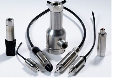
구성품간의 모듈을 기반으로 Druck사의 실리콘 센싱소자 기술, 아날로그 전기회로 기술이 총집결된 제품입니다.
이러한 modular design 생산방식으로 기존의 제품보다 납기가 획기적으로 짧아지게 되었습니다.
높은 정확도와 고객이 요청하는 Spec은 이러한 기본 구성 부품들로 제조되어 소비자 맞춤형 압력센서가 가능토록 합니다
일반적인 application은 가스 & 오일, 자동차 분야, 항공분야 뿐만 아니라 현장의 공압 / 유압 설비의 테스트 설비에도
적합하도록 설계 되었습니다.
High Quality Piezo-Resistive Sensor
- Stainless Steel module
- Analogue 전자 기술
(1) 빠른 turn on
(2) 응답속도: 5kHz
(3) 낮은 noise
- 정확도: ±0.04 % FS BSL
- 안정도: ±0.05 % FS / Year
Flexible Platform
- 압력 연결 fitting
- 압력 범위
- 출력 신호 타입
- 출력 커넥터 타입
- 온도 보상 범위
- 정확도
Short Lead Times
- 상호 결합이 가능한 모든 모듈 부품의 stock 보유
- 고객 요구에 맞게 구성품 조립 생산 가능
Price Advantage
- 소량주문 가능
- 기본 Module 구성품으로부터 제조되는 다양한 변화로 최적 금액 선택 가능


Measurement
Gauge ranges
Any zero based range between 70 mbar and 70 bar
(1 to 1,000 psi) (values inpsi are approximate)
Sealed Gauge Ranges
Any zero based range between 10 and 700 bar
(145 to 10,000 psi)Absolute Ranges
Any zero based range between 350 mbar and 700 bar (5 to 10,000 psi)
Operating Pressure Range
Differential Ranges
Wet/Dry
Uni-directional or bi-directional 70 mbar to 35 bar (1 to 500 psi)
Wet/Wet
Uni-directional or bi-directional 350 mbar to 35 bar (5 to 500 psi)
Line pressure: 70 bar max (1000 psi)Barometric Ranges
Barometric ranges are available with a minimum span of 350 mbar (5.1 psi)
Non Zero Based Ranges
Non zero based ranges are available. Contact
GE to discuss your requirementsOver Pressure
• 10 × FS for ranges up to 150 mbar (2 psi)
• 6 × FS for ranges up to 700 mbar (10 psi)
• 2 × FS for barometric ranges
• 4 × FS for all other ranges (up to 200 bar for ranges ≤70 bar and up to 1200 bar for ranges >70 bar) For differential versions the negative side must notexceed the positive side by more than:
• 6 × FS for ranges up to 150 mbar (2 psi)
• 4 × FS for ranges up to 700 mbar (10 psi)
• 2 × FS for all other ranges up to a maximum of 15 bar (200 psi)
Containment Pressure
Gauge, Sealed Gauge, Absolute and Differential (+ve port):
• 6 × FS for ranges up to 70 bar (1000 psi) (200 bar (2,900 psi) maximum)
• 6 × FS for ranges above 70 bar (1000 psi) (1200 bar (17,000 psi) maximum)
Differential (-ve port) must not exceed positive port by more than 4 × FS (15 bar (200 psi) maximum)
Supply and Outputs
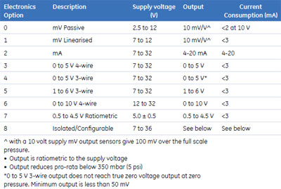
Isolated/Configurable
(Option 8)
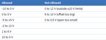
Any pressure signal output configurations will be available, subject to the following limitations:
• Minimum span: 2 V
• Maximum span: 20 V
• Output limits: ±10 V
• Maximum zero offset: ≤ span
Reverse output response to pressure is available.The output will continue to respond to 110% FS. i.e. if a 0 to 10 V output is specified, the output will continue to increase proportionally to applied pressure until at least 11 V. Current consumption is <20 mA @ 7 Vdc supply, reducing to <5 mA @ 32 Vdc supply. On startup <100 mA drawn for 10 ms typically.
Example
Power-Up Time
mV, Voltage and current versions: 10 ms
Isolated/configurable version: 500 ms
Shunt Calibration
Shunt Calibration provides customer accessible connections which, when shorted together, cause a shift in output of 80% FS in order to simulate applied pressure. It is fitted to the mV and Isolated/Configurable versions as standard. It is not available with a DIN electrical connector (Option 7).
Performance
Accuracy
Voltage, Currentand mV
Linearised
Combined effects of non-linearity, hysteresis andrepeatability:
Industrial: ±0.2% FS BSL
Improved: ±0.1% FS BSL
Premium: ±0.04% FS BSLmV Passive
≤ 70 bar
Industrial: ±0.2% FS BSL
Improved: ±0.1% FS BSL> 70 bar
Industrial: ±0.5% FS BSL
Improved: ±0.5% FS BSLZero Offset
and Span Setting
Voltage and Current Outputs
Adjustable Zero and Span Connector Versions
Adjustable electrical connector options allow access to potentiometers that give at least ±5% FS adjustment (see Electrical Connector section)Factory set to:
Industrial: ±0.5% FS
Improved: ±0.2% FS
Premium: ±0.2% FSFixed Zero and Span Connector Versions
All specifications: ±1% FS
mV Outputs
All specifications ±3 mV
Long Term Stability
±0.05% FS typical (±0.1% FS maximum) per year increasing pro-rata for pressure ranges below 350 mbar
Temperature Effects
Four compensated temperature ranges can be chosen.
Industrial Accuracy performance:
-10 to +50 °C (-14 to +122 °F): ±0.75% FS, Temperature error band (TEB)
-20 to +80 °C (-4 to 176 °F): ±1.5% FS TEB
-40 to +80 °C (-40 to 176 °F):: ±2.25% FS TEB
-40 to +125 °C (-40 to 257 °F): ±2.25% FS TEBImproved and Premium Accuracy performance:
-10 to +50 °C (-14 to +122 °F): ±0.5% FS TEB
-20 to +80 °C (-4 to 176 °F): ±1.0% FS TEB
-40 to +80 °C (-40 to 176 °F): ±1.5% FS TEB
-40 to +125 °C (-40 to 257 °F): ±1.5% FS TEBTemperature effects increase pro-rata for pressure ranges below 350 mbar (5 psi) and are doubled for barometric ranges.
Physical Envir
Environmental Protection
• See Electrical Connector section
• Hyperbaric Pressure: 20 bar (300 psi) maximumOperating
Temperature Range
See Electrical Connector section
Pressure Media
Fluids compatible with Stainless Steel 316L and Hastelloy C276.
For the wet/dry differential version, the negative pressure port:
fluid compatible with stainless steel 316L, pyrex, silicone and structured adhesive.Pressure Connector
• G1/4 female*
• G1/4 male flat
• G1/4 male 60° internal cone
• G1/8 male 60° internal cone
• 1/4 NPT female*
• 1/4 NPT male
• 1/8 NPT male
• M20 x 1.5 male
• M14 x 1.5 60° internal cone
• M12 x 1 60° internal cone
• 7/16-20 UNF male
• G1/2 Male via welded Adaptor*
• 1/2 NPT Male via welded Adaptor*
• Depth Cone (G1/4 female)
Choose connectors marked * for pressure ranges over 70 bar.
Certification
• CE Marked
• RoHS
• EMC Standards
• BS EN 61000-6-2:2005 Susceptibility – Heavy Industrial (except mV versions)
• BS EN 61000-6-3:2007 Emissions – Light Industrial
• BS EN 61000-6-4:2007 Emissions – Heavy Industrial
• BS EN 61326-1:2006 Electrical Equipment for Measurement, Control and Laboratory Use – EMC requirementsBS EN 61000-6-1: 2007 Susceptibility – Light Industrial
견적 및 상담문의 | QnA
*개발문의등 질문을 남겨주시면
빠른 답변 드리겠습니다.

부산광역시 사상구 대동로 303 (감전동 벽산디지털밸리 621호) | 전화 : 051-329-7600 | 팩스: 051-329-7602
광주사업소 주소 : 광주광역시 북구 운용로 75 (트라움시티 414호) | 전화 : 062-511-7608 | 팩스: 062-511-7609
광주사업소 주소 : 광주광역시 북구 운용로 75 (트라움시티 414호) | 전화 : 062-511-7608 | 팩스: 062-511-7609
POWER by PICELL.BIZ


